
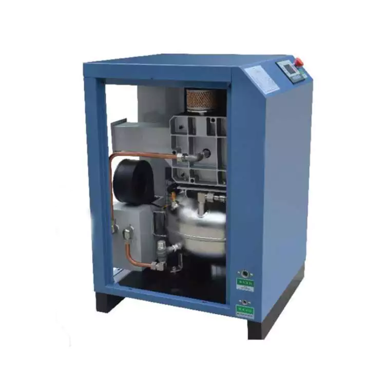
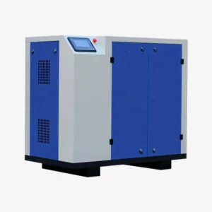
EP-CMW18-1.0 Oil-Free Scroll Air Compressor
The EP-CMW18-1.0 is Ever Power’s highest-capacity 1.0 MPa oil-free scroll compressor — four 4.5 kW scroll heads in one intelligent cabinet delivering 1640 L/min of certified oil-free air, with four-stage demand management, N+3 redundancy architecture, and the operational simplicity of a single control interface for facilities that treat compressed air as critical infrastructure.
EP-CMW18-1.0: Specifying a Central Oil-Free Compressed Air Station at 1.0 MPa
The language used when specifying compressed air changes at this capacity level. A facility that needs 1640 L/min of oil-free air at 1.0 MPa is not selecting a machine -- it is designing a compressed air infrastructure. The questions shift from "what compressor fits in the corner?" to: what is the redundancy architecture? How does the system respond to one head's failure at 2 am? What does single-point maintenance look like? How does one control interface manage four independent compression mechanisms? And what does the air quality specification look like when it is documented for a regulatory submission?
The EP-CMW18-1.0 is designed to answer all of those questions with a single installation. Four 4.5 kW scroll air-ends in one managed cabinet produce up to 1640 L/min of certified oil-free air at working pressures from 0.2 to 1.0 MPa. The four-head architecture delivers N+3 redundancy: even with three heads simultaneously offline -- an extraordinary scenario -- the fourth head continues supplying 410 L/min. The touch-screen PLC manages four-stage demand sequencing, four-way lead rotation, and individual per-head maintenance scheduling from one interface. All four air-ends carry the 2-year warranty. View the complete capacity range at the full EP-CMW product page.
Designing a Central Air Station Around the EP-CMW18-1.0
At 1640 L/min and 1.0 MPa, the EP-CMW18-1.0 is typically the primary compressed air source for a ring main or branched distribution system serving multiple production zones, buildings, or process areas. The engineering considerations that apply at this scale are different from those relevant to point-of-use compressors.
Single connection point, single control interface, single maintenance record -- regardless of how many distribution branches or production zones the compressed air system serves.
Pipe sizing: At 1640 L/min, the distribution main diameter needs to be specified for the actual peak flow velocity to avoid excessive pressure drop. The 1-inch stainless steel outlet on the EP-CMW18-1.0 connects to the distribution header, but the header diameter should be engineered for the total system flow at the maximum run length. Ever Power's application team can provide pressure drop guidance for common header configurations.
Receiver sizing: A well-sized compressed air receiver downstream of the EP-CMW18-1.0 buffers demand peaks between head start/stop events, reduces pressure variation in the distribution system, and allows the PLC to use longer averaging windows for head sequencing decisions. For a 1640 L/min system, a receiver volume in the range of 500 to 1000 litres is typical -- exact sizing depends on the demand profile and allowable pressure band.
Redundancy documentation: For pharmaceutical, medical, and food safety applications where compressed air system redundancy must be documented in validation or audit submissions, the four-head architecture of the EP-CMW18-1.0 provides a formal N+3 redundancy claim: the system maintains compressed air supply even with three of four heads unavailable. This is the highest redundancy level achievable in a single-cabinet oil-free scroll compressor.
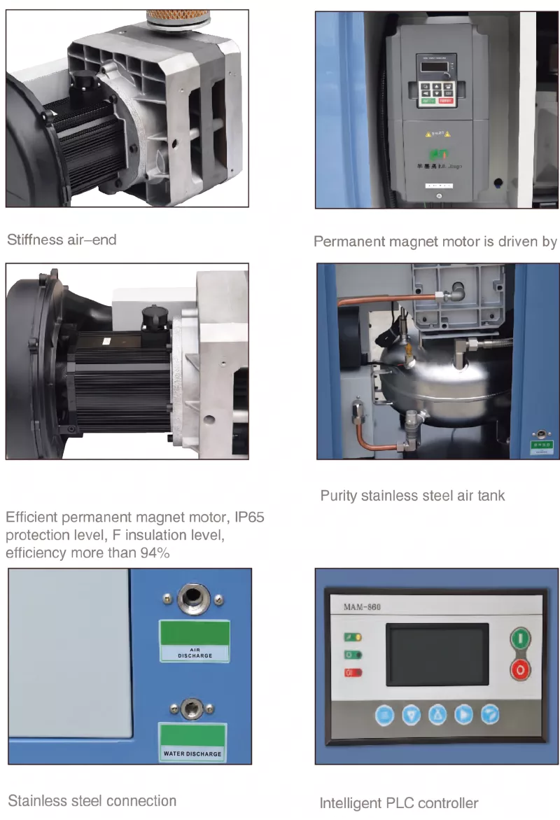
Four Capacity Stages: Matching Infrastructure Scale to Production Reality
Four heads at 4.5 kW each give the EP-CMW18-1.0 four distinct operating points -- each corresponding to a meaningful production scenario. The PLC navigates between them automatically, but understanding which stage maps to which operational context helps facilities teams set maintenance windows and plan capacity headroom correctly.
Stage 1 -- One Head: 410 L/min at 1.0 MPa (4.5 kW)
Night shift, weekend building services, low-demand maintenance air. Three heads on standby, fully rested and immediately available if demand rises.
Stage 2 -- Two Heads: 820 L/min at 1.0 MPa (9 kW)
Single-shift partial production, cleaning operations, instrument air distribution to areas not in active production. Two heads on standby.
Stage 3 -- Three Heads: 1230 L/min at 1.0 MPa (13.5 kW)
Full single-shift production across all process areas. One head on standby -- available immediately if demand spikes or a head fault occurs.
Stage 4 -- Four Heads: 1640 L/min at 1.0 MPa (18 kW)
Peak double-shift production, shift changeover peaks, seasonal high-demand periods. Full capacity with no standby -- the scenario for which the system is sized.
The PLC transitions between stages without operator input. All four transitions use sequential head starting to prevent simultaneous inrush current events. The system can be configured with tight or wide pressure bands depending on the application's pressure tolerance: a narrow band (e.g., 0.85-1.00 MPa) minimises pressure variation at the cost of more frequent head cycling; a wider band (e.g., 0.75-1.00 MPa) reduces cycling frequency at the cost of slightly greater pressure variation in the distribution system.
Why Oil-Free Matters More at Central Station Scale
At point-of-use compressor scale, oil contamination risk is localised. A single machine supplying one or two pieces of equipment creates a contained contamination event if the air quality fails. At central station scale -- one compressor supplying a ring main that feeds 20 or 50 or 100 connected devices across multiple production zones -- an oil contamination event becomes a system-wide event. Every connected process, instrument, and pneumatic tool is simultaneously affected. The investigation, cleaning, and revalidation scope is correspondingly larger.
The EP-CMW18-1.0 eliminates this risk category entirely. Because no lubricant enters the compression chamber at any stage -- in any of the four heads, at any operating point -- the compressed air delivered to the distribution system is structurally oil-free. Not filtered oil-free. Not reduced-oil-content. Structurally oil-free, regardless of which heads are running or what the ambient conditions are. For central station applications serving food production, pharmaceutical manufacturing, or medical instrument air, this distinction removes an entire category of system risk from the facility's compressed air quality management programme.
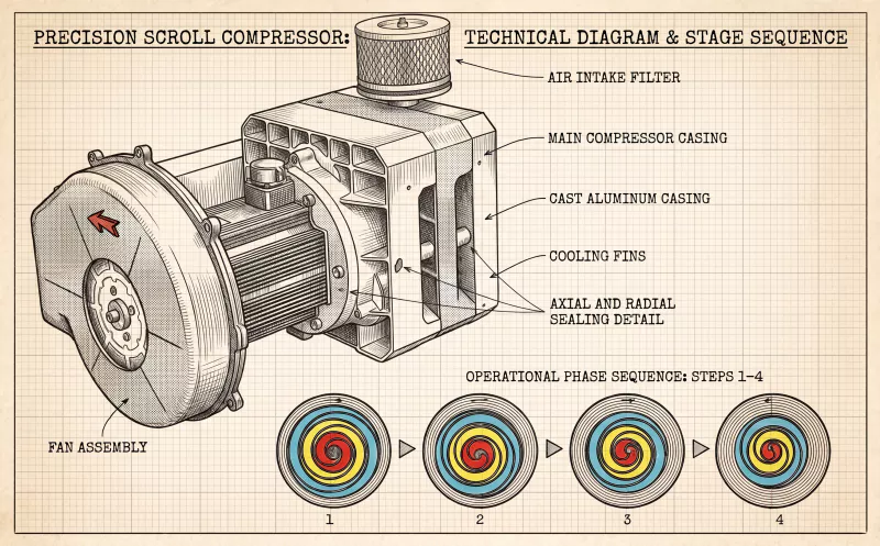
The stainless steel air-contact surfaces -- including the common manifold, all internal pipework, and the 1-inch outlet -- extend this quality assurance through the compressor itself and to the point of connection with the distribution system. Combined with the 1 micron inlet filter on each of the four heads, the compressed air pathway from atmosphere to outlet is designed to introduce no contamination of any kind.
Technical Specifications
| Parameter | Specification |
|---|---|
| Model | EP-CMW18-1.0 |
| Configuration | Quad Air-End (4 x 4.5 kW scroll heads) |
| Total Motor Power | 18 kW / 25 HP |
| Working Pressure Range | 0.2 - 1.0 MPa |
| Free Air Delivery (FAD) | 1640 L/min (at rated 1.0 MPa) |
| Capacity Steps | 410 / 820 / 1230 / 1640 L/min (1 / 2 / 3 / 4 heads) |
| Noise Level | 61 +/- 3 dB(A) |
| Outlet Connection | 1 inch stainless steel |
| Weight | 350 kg |
| Dimensions L x W x H | 1450 x 900 x 1150 mm |
| Air-End Warranty | 2 Years per head |
| Redundancy Level | N+3 (system continues on any single head) |
| Motor Type | Permanent Magnet x4, IP65, F-class, >94% efficiency each |
| Drive | Direct Drive per head (no belt, no coupling) |
| Control | Touch-screen PLC: 4-stage demand, 4-way head rotation, per-head maintenance alerts, sequential start |
| Air-Contact Surfaces | Stainless Steel throughout |
| Inlet Filtration | 1 micron per head (independent) |
| Lubrication | Oil-Free -- annual bearing grease per head only |
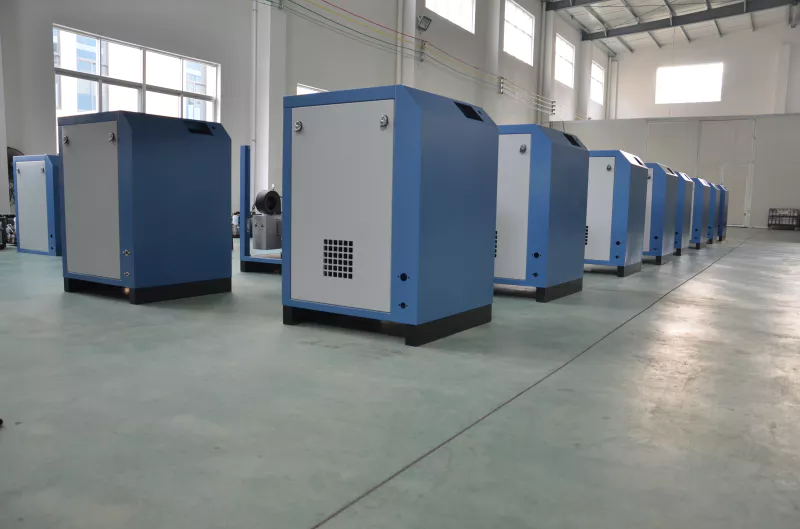
How Three Facilities Use the EP-CMW18-1.0 as Central Infrastructure
United Kingdom -- Large Hospital Medical Air Campus
N+3 Redundancy Documented in Medical Air System Validation Report
A large NHS hospital trust in England replacing the central instrument air system for a three-wing surgical complex needed to document compressed air redundancy formally in their HTM 02-01 compliant system validation report. Their biomedical engineering team specified N+3 redundancy as a minimum requirement -- the system must continue supplying instrument air even if three of four compressor units are simultaneously unavailable. The EP-CMW18-1.0 was the only single-cabinet oil-free scroll solution capable of meeting this specification. The four-head architecture provided the required N+3 claim, the oil-free output met the HTM medical air purity standard without a separate medical air processor, and the single PLC control interface simplified the maintenance documentation to a single system record covering all four heads. In 30 months of operation, the unit has required four individual head maintenance events -- none of which interrupted instrument air supply to any surgical suite.
★★★★★
"N+3 in a single cabinet, HTM-compliant without an air processor, and 30 months of operation without a single supply interruption. This is exactly what we specified." -- Biomedical Engineering Lead
France -- Pharmaceutical Sterile Manufacturing Campus
Central 1.0 MPa Air Station for Multi-Suite Aseptic Operations
A French CMO (contract manufacturing organisation) producing injectable biologics across four aseptic suites required a central compressed air source that could supply all four suites simultaneously at 1.0 MPa, maintain supply continuity during head maintenance without batch interruption, and produce output with a documented oil-free specification that would withstand EU GMP Annex 1 regulatory scrutiny. The EP-CMW18-1.0 supplied the 1640 L/min needed for simultaneous four-suite operation. During the first scheduled maintenance cycle, one head was serviced per quarter with three heads maintaining supply throughout. The quality team incorporated the compressor's structural oil-free specification directly into the compressed air system validation protocol, eliminating the oil content testing frequency previously required for the oil-injected system it replaced.
★★★★★
"Four aseptic suites on one oil-free central station. GMP Annex 1 audit passed with specific positive comment on the compressed air system validation approach." -- Quality Assurance Director
Australia -- Multi-Building Food Manufacturing Campus
Single Central Compressor Replacing Five Distributed Units Across Three Buildings
A food manufacturing campus in Queensland producing dairy, beverage, and prepared food products across three buildings had been running five separate oil-free compressors -- one or two per building -- with no central coordination. Peak demand spikes in one building had no relationship to capacity availability in another. Maintenance was handled by whichever building's team was available. Air quality was consistent within buildings but unverified across the campus. The EP-CMW18-1.0 connected to a new ring main serving all three buildings replaced all five units. Four-stage PLC management handled the campus demand profile -- typically two heads during day shifts, three during production peaks, one overnight. The facilities manager reported that the campus compressed air electricity bill fell by 28% in the first year, BRC audit compliance improved from a medium finding (oil risk) to a full clean pass, and the maintenance team went from five separate service records to one.
★★★★★
"Five units, five service records, inconsistent pressure between buildings, a BRC finding every audit. Now: one unit, one record, consistent pressure everywhere, and a clean BRC pass." -- Campus Facilities Manager
Frequently Asked Questions -- EP-CMW18-1.0
How is N+3 redundancy defined and how does the EP-CMW18-1.0 achieve it?
N+3 redundancy means the system continues to function even with three of its four components simultaneously unavailable. In the EP-CMW18-1.0, N is 1 (the minimum number of heads needed to maintain compressed air supply) and the three additional heads provide the +3 cushion. In practice, losing three heads simultaneously is an extraordinary scenario -- but for regulatory submissions in pharmaceutical and medical applications, the formal N+3 claim is the specification that must be met, and this unit meets it.
What receiver size is recommended for a central station installation?
For a central station serving multiple zones at 1640 L/min peak demand, a receiver volume of 500 to 1000 litres downstream of the compressor outlet is a common starting range. Exact sizing depends on your allowable pressure band, the distribution pipe volume, and the peak demand duration. Ever Power's application engineering team can provide sizing guidance based on your specific system parameters.
How does the PLC handle a head fault during full four-head operation?
If any head develops a fault condition during operation, the PLC immediately stops that head, logs the fault with an error code and timestamp, and displays a specific fault alarm on the touch-screen. The remaining three heads continue operating normally. The system automatically adjusts its demand-sequencing logic to use the three remaining heads to maintain system pressure. If the fault head was the lead unit, the PLC promotes the next head in the rotation sequence to lead.
Can the pressure setpoints be configured for tight-tolerance instrument air applications?
Yes. The PLC pressure setpoints that trigger head start and stop events are configurable within the commissioning settings. For instrument air applications requiring tight pressure tolerance -- such as analytical instrumentation or precision pneumatic actuation -- the operating band can be set narrower, with the understanding that more frequent head cycling will result. Ever Power's commissioning team sets and documents the initial configuration for your application.
How does the four-way head rotation affect the maintenance planning cycle?
The PLC distributes running hours equally across all four heads through automatic lead rotation. Over a full operating cycle, all four heads accumulate comparable hours and approach their maintenance intervals within a relatively short window of each other. This concentrates scheduled maintenance into a predictable annual or biannual pattern rather than generating continuous staggered maintenance events. Facilities with fixed maintenance windows -- common in pharmaceutical and food manufacturing -- find this predictability significant for resource planning.
Specifying the EP-CMW18-1.0 for Your Facility
The EP-CMW18-1.0 is a capital investment in compressed air infrastructure, not a point-of-use appliance. The decisions made at specification stage -- receiver sizing, distribution pipe sizing, pressure setpoint configuration, redundancy documentation format, and maintenance scheduling approach -- determine how well the unit serves the facility across its operational lifetime. Ever Power's application engineering team is equipped to work through these decisions with your facilities engineering team, compressed air system designer, or EPC contractor.
Learn more about Ever Power's manufacturing and engineering capabilities on our company page, or review all capacity and pressure options in the complete EP-CMW product range to confirm that the EP-CMW18-1.0 is the right configuration for your application.
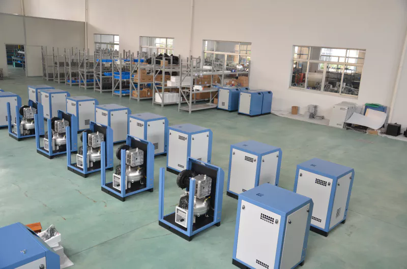
Factory tour


Related Products
-
CM/PV permanent magnet variable frequency oil-free screw air compressor
-
CM/PV permanent magnet variable frequency oil-free screw air compressor
-
CM/GPV medium pressure permanent magnet variable frequency oil-free screw air compressor
-
CM/G medium pressure industrial frequency oil-free screw air compressor