
Walk through any PET bottle blowing plant that has operated for more than a decade, and the compressor room tells a familiar story: a row of reciprocating piston compressors, some dating back fifteen years or more, each serving a portion of the plant’s high-pressure air demand. The machines are noisy — typically 85–95 dB(A) per unit. Maintenance teams service them on rotating schedules. Valve assemblies, piston rings, and cylinder liners come and go. Oil changes happen every few hundred hours. Condensate separators need monitoring. And despite all this activity, the air quality remains oil-dependent, the energy consumption remains high, and the plant manager wonders whether there is a better way.
There is. A single water-lubricated oil-free single-screw compressor can replace a bank of reciprocating piston units, delivering higher air quality, lower noise, dramatically reduced maintenance requirements, and improved energy efficiency — from one machine, with one control system, and one maintenance schedule. This article explains how that replacement works in practice, what to evaluate during the specification process, and what facilities typically find after the transition is complete.
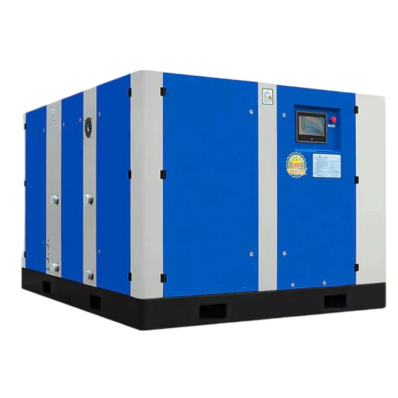
Why Piston Compressors Accumulate in PET Blowing Plants
Reciprocating piston compressors were the original technology for high-pressure PET blowing air. When PET bottle manufacturing expanded in the 1990s and 2000s, piston compressors were the only commercially available option for reaching 30–40 bar at reasonable cost. Facilities added units as production grew — one machine per blowing line, or one machine per shift requirement. Over time, the compressor room filled up.
The piston compressor’s multi-stage design (typically three or four stages to reach 40 bar) generates significant heat at each stage boundary, produces substantial noise and vibration, consumes considerable energy during unloaded running, and requires frequent maintenance of valves, piston rings, and cylinder surfaces. Each unit has its own oil circuit, its own condensate management requirement, and its own service schedule. Managing ten units means managing ten overlapping maintenance schedules, ten sets of spare parts inventories, and ten potential sources of oil contamination in the compressed air supply.
The Single-Screw Water-Lubricated Alternative
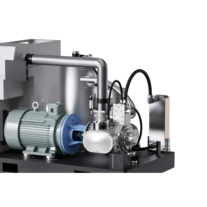
The water-lubricated single-screw compressor operates on a fundamentally different mechanical principle. A single main screw meshes with two star wheels positioned symmetrically on opposite sides. Pure water injected into the compression chamber lubricates the screw-star wheel contact, seals the compression clearances, cools the process to near-ambient temperature, and removes compression heat continuously. The result is single-stage compression to 40 bar — no intercoolers, no multi-stage valves, no piston rings — from one continuous orbital compression cycle.
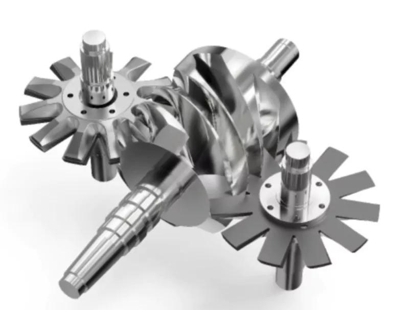
The balanced force geometry of the single-screw design — radial loads from both star wheels cancel each other across the main screw shaft — allows the air end to operate at approximately 3,000 rpm with minimal bearing load. At this rotational speed and load condition, the air end is rated for a design service life exceeding 25 years of continuous 7×24 operation. This is a structural longevity advantage over both piston compressors and twin-screw designs that operate at much higher speeds under much higher bearing loads.
Step 1: Quantify Your Existing Demand
The starting point for a replacement project is accurate measurement of your current compressed air demand. This means three things:
- Peak flow rate (m³/min or cfm): The maximum combined output of all your existing piston units when running simultaneously at full load. This is the ceiling your replacement unit must match or exceed.
- Average flow rate across the production shift: This determines whether a variable-speed (VSD) compressor can deliver meaningful energy savings. If your demand profile varies significantly between production peaks and changeover periods, a VSD model reduces electricity consumption at partial load.
- Required working pressure: Not the maximum rated pressure of your existing compressors, but the actual minimum working pressure required at the blow mold inlet under full production conditions, accounting for distribution system pressure losses.
Many facilities find that their ten piston units are not all running simultaneously in practice. Three to six may be in active production service at any time, with the remainder on standby or in various stages of maintenance. The actual peak demand is therefore lower than the nameplate capacity of the entire bank — and the replacement compressor can be sized to actual demand rather than theoretical maximum nameplate output.
Step 2: Select the Right Model
Water-lubricated single-screw compressors for PET blowing are available in a range of output capacities. The selection criteria are straightforward once the demand measurement is complete:
| Your Demand Profile | Recommended Configuration | Reason |
|---|---|---|
| Steady, near-constant full-load | Fixed-frequency single motor | Maximum simplicity, no VSD components |
| Variable — 40–100% range | VSD single or dual motor | Up to 35% energy saving at partial load |
| Very high demand + redundancy needed | Dual-motor VSD | 50% capacity continues on motor fault |
| Multiple lines at different pressures | Full pressure range model (2.0–4.0 MPa) | One machine covers all pressure requirements |
The replacement compressor should be sized to your measured peak demand plus a 10–15% margin for production growth and pressure loss compensation. Oversizing beyond this margin wastes capital and reduces VSD energy efficiency benefits at partial load.
Step 3: Plan the System Integration
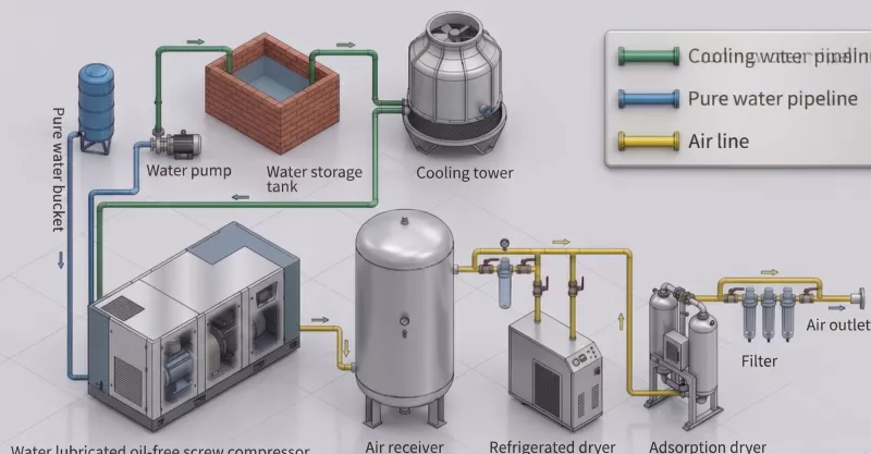
A water-lubricated single-screw compressor requires the same downstream treatment as any high-pressure compressed air system supplying PET blowing equipment: an air receiver for pressure buffering, a refrigerated dryer to reduce moisture to the required dew point, and particulate filtration before the blow mold inlet. What it does not require is the oil separator, coalescing filter, and activated carbon adsorber that an oil-injected system needs — simplifying the downstream train and reducing the number of maintenance points.
Water-cooled models connect to a facility cooling water circuit or cooling tower. Air-cooled models are self-contained and require only electrical connection and compressed air outlet piping — the right choice for facilities without cooling water infrastructure. The compressed air distribution piping from the existing piston compressor bank can typically be reused, connecting to the new compressor outlet via a single connection point rather than the multiple branch connections of the original multi-unit installation.
What Changes After Replacement
Facilities that have completed this replacement consistently report the same set of operational changes:
- Noise reduction of 20–25 dB(A): A bank of piston compressors typically generates 88–95 dB(A) in aggregate. A single water-lubricated screw compressor of equivalent output operates at 70–75 dB(A). This reduction is significant enough to change hearing protection requirements and make the compressor room a more tolerable working environment.
- Maintenance workload reduction of 60–80%: From rotating service schedules across ten machines to a single annual maintenance event covering one air filter, one water filter, and a bearing grease check. No oil changes. No valve assemblies. No piston rings. No condensate separator inspections.
- Oil contamination risk eliminated: The structural oil-free guarantee of water lubrication means the entire downstream compressed air quality concern associated with filter maintenance compliance is removed from the facility’s risk register.
- Energy consumption reduction of 10–35%: The isothermal compression effect of water lubrication reduces specific energy by more than 10% versus the adiabatic multi-stage piston process. VSD models add a further 20–35% reduction at partial load.
- Compressor room reclaimed: Ten piston units occupy far more floor space than one screw compressor of equivalent output. The recovered space is frequently repurposed for production equipment or storage.
A Representative Replacement Example
A PET bottle blowing plant producing edible oil bottles ran eight reciprocating piston compressors, each rated at approximately 1.0 m³/min at 38 bar. Combined peak output: 8.0 m³/min. Actual measured peak demand during production: 6.8 m³/min. Noise level in compressor room: 92 dB(A). Annual maintenance events across eight units: over 40 individual service interventions. Oil-related quality alerts in the previous 24 months: three batch investigations.
Replacement specification: one water-lubricated single-screw VSD compressor rated at 8.2 m³/min at 40 bar. Outcome after 18 months of operation: compressor room noise at 72 dB(A). Annual maintenance events: two (one air filter, one water filter and bearing service). Oil-related quality alerts: zero. Energy consumption: 18% lower than the eight-unit bank at equivalent output. Floor space recovered: sufficient for two additional palletising stations.
Planning Your Own Replacement Project
The key steps for a successful transition from a piston compressor bank to a single water-lubricated screw unit are: measure actual peak and average demand accurately; specify the replacement model with a 10–15% capacity margin; plan the downstream treatment train for the new system (simpler than the existing filtration chain); confirm cooling requirements and utility connections; and schedule the cutover during a planned maintenance window to minimise production impact.
Ever Power’s engineering team provides application-specific sizing support, demand profile analysis, and complete system configuration proposals for replacement projects across all CMG series models — from 75 kW single-motor units through to 320 kW dual-motor flagship configurations. Contact us to discuss your specific installation and receive a detailed replacement assessment.