
Wall thickness variation in PET bottles is one of the most persistent quality challenges in stretch blow molding. It affects structural integrity under drop and compression testing, causes fill-level inconsistencies in volumetric filling lines, creates labelling difficulties on bottles with irregular sidewall geometry, and increases material consumption when minimum wall thickness requirements force an upward adjustment of average wall weight. When quality engineers investigate the cause of wall thickness variation, the investigation typically begins at the preform, the stretch rod, the heating oven, and the mold — and often stops there, having identified one or more contributing factors without addressing the compressed air system at all.
This is a systematic gap. Compressed air pressure instability is one of the most significant and most underdiagnosed contributors to PET bottle wall thickness variation — and it is a problem with a clear technical cause and a straightforward engineering solution.

How Compressed Air Pressure Affects Wall Thickness Distribution
In the stretch blow molding process, wall thickness distribution is determined by the balance between the rate of axial stretching (controlled by the stretch rod) and the rate of radial expansion (driven by the compressed air pressure). These two forces act simultaneously during the blow cycle, and the ratio between them determines how the PET material distributes across the mold geometry.
When main blowing air pressure drops below the setpoint — even briefly, by 1–3 bar — the radial expansion force decreases. The material that would have been pushed against the mold sidewall instead remains thicker in the mid-body region, while the shoulder and base sections, which receive the initial burst of higher-pressure air, may be relatively thinner. The result is a bottle with a non-uniform wall thickness profile that is consistent across the affected production run — a systematic defect, not a random one.
When main blowing air pressure is unstable — fluctuating ±2–5 bar around the nominal setpoint — the wall thickness variation becomes cycle-to-cycle rather than systematic. Bottles produced during high-pressure cycles will have different wall distributions than bottles produced during low-pressure cycles. On a high-speed rotary machine producing 20,000+ bottles per hour, even brief pressure fluctuations affect hundreds of bottles before the instability is detected through quality sampling.
Sources of Pressure Instability in the Compressed Air System
Pressure instability at the blow mold inlet can originate from several points in the compressed air supply chain. Understanding the source is essential to selecting the correct corrective action.
1. Compressor Pressure Band Control Width
Fixed-frequency compressors operate in an on/off or load/unload cycle. When the system pressure falls to the lower setpoint, the compressor loads; when it rises to the upper setpoint, it unloads. The pressure band between these two points — typically 1–2 bar for well-maintained systems, wider for older or poorly calibrated units — means system pressure is continuously cycling within this range. If the pressure band is too wide, the variation at the blow mold inlet exceeds the tolerance required for consistent wall thickness.
VSD compressors with active pressure band control maintain system pressure within ±0.1 MPa (±1 bar) of the setpoint by continuously adjusting motor speed rather than switching between full load and full unload. This tighter pressure control directly reduces the contribution of the compressor to wall thickness variation — the mold inlet pressure is more stable, and the blow cycle outcome is more consistent.
2. Inadequate Air Receiver Volume
The air receiver between the compressor and the blow molding machine serves as a pressure buffer — absorbing the pulsed demand of the blowing cycle and presenting a stable pressure to the distribution system. An undersized receiver allows the rapid demand pulses of a high-speed rotary machine to propagate upstream and cause pressure drops in the supply header.
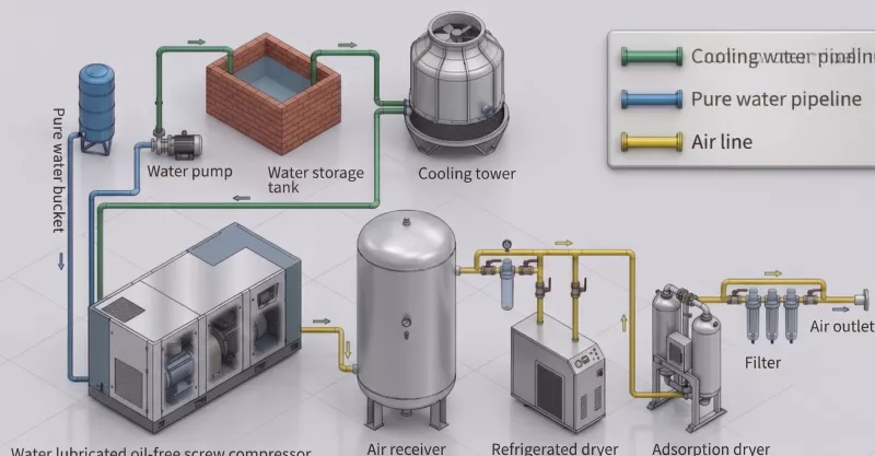
The minimum recommended receiver volume for PET blowing applications is 10–15 times the compressor’s per-minute output in litres. For a compressor delivering 8 m³/min (8,000 L/min), the minimum receiver volume is 80,000–120,000 litres (80–120 m³). Many installations use significantly undersized receivers — often sized for general industrial applications rather than the specific pulsed demand profile of blow molding — and the resulting pressure instability contributes directly to wall thickness variation.
3. Distribution Piping Pressure Losses
Pressure losses in the compressed air distribution piping between the compressor and the blow molding machine reduce the effective pressure at the mold inlet below the compressor setpoint. These losses are calculable and manageable, but they are frequently underestimated — particularly in older facilities where the piping layout has evolved incrementally and the original design parameters no longer reflect the actual system configuration.
Common sources of distribution pressure loss in PET blowing systems include undersized main distribution headers, excessive use of quick-connect fittings (which have high pressure drop coefficients), undersized flexible hoses between the hard piping and the machine connection, and partially closed isolation valves that were left in a throttled position and never fully reopened. A site survey of the distribution system — measuring actual pressure at the machine inlet and comparing it to the compressor outlet — quantifies the total distribution loss and identifies the specific components responsible.
4. Multiple Compressors Without Coordinated Control
Facilities operating multiple compressors in parallel to supply a high-speed blowing line often experience pressure instability from uncoordinated compressor control. When two fixed-frequency compressors both attempt to maintain pressure within their respective control bands, their load/unload cycles can interact in ways that produce pressure oscillations rather than stable supply. This is a well-documented phenomenon in multi-compressor systems without master control coordination, and it is most pronounced when the compressors have slightly different pressure setpoints or control hysteresis values.
The solution is either a master compressor controller that coordinates the load/unload sequencing of all units, or replacement of the multi-unit configuration with a single VSD compressor with active pressure band control — which eliminates the coordination problem entirely by providing continuous rather than on/off pressure regulation.
Diagnosing Compressor-Related Wall Thickness Issues
Before attributing wall thickness variation to the compressed air system, it is important to confirm the correlation. The following diagnostic approach helps distinguish compressor-related causes from preform, oven, or mold-related causes:
- Install a data-logging pressure gauge at the blow mold inlet (not at the compressor outlet) and record pressure over a full production shift at 1-second or faster sampling intervals. This provides the actual pressure profile at the point where it matters, including any fluctuations that the compressor outlet gauge or PLC display may not reveal.
- Correlate the pressure log with wall thickness measurements taken from sequentially produced bottles. If wall thickness variation follows the pressure variation pattern in the log, the compressed air supply is a primary contributor.
- Identify the pressure instability source by comparing pressure at the compressor outlet, at the receiver outlet, at the main distribution header, and at the machine inlet. The point where pressure variation increases identifies the system section responsible.
- Check compressor control settings: Verify that the pressure band (difference between load and unload setpoints) is within the manufacturer’s minimum specification. On older compressors, this band may have widened due to control system drift or intentional adjustment to reduce compressor cycling frequency.
Engineering Solutions for Stable Blow Pressure
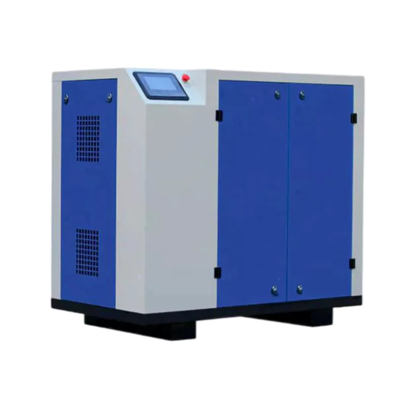
Once the diagnosis confirms compressor-related pressure instability as a wall thickness contributor, the engineering solutions are well established:
Upgrade to VSD compressor control: Replace fixed-frequency on/off control with a VSD compressor maintaining pressure within ±0.1 MPa of the setpoint through continuous speed modulation. This is the single most effective improvement for eliminating compressor-related pressure fluctuations at the blow mold inlet.
Increase receiver volume: Adding receiver volume in parallel with the existing receiver is a low-cost intervention that improves pressure stability immediately by increasing the buffer capacity between the compressor and the pulsed demand of the blow molding machine. This is particularly effective when the compressor itself is well-controlled but the receiver is undersized for the actual demand profile.
Audit and rectify distribution losses: Systematically measure and correct pressure losses in the distribution system. Upgrade undersized pipework sections, replace high-loss fittings with lower-drop alternatives, and verify all isolation valves are fully open.
Consolidate multi-compressor systems: Where multiple compressors are contributing to pressure instability through uncoordinated control, replacing the bank with a single VSD compressor eliminates the coordination problem and typically improves pressure stability significantly while reducing maintenance complexity.
The relationship between compressed air pressure stability and PET bottle wall thickness quality is direct and quantifiable. Facilities that have addressed compressor-related pressure instability as part of a systematic quality improvement programme consistently report both improved wall thickness uniformity and reduced material consumption — thinner average walls become achievable once the statistical spread of wall thickness measurements narrows sufficiently to maintain the minimum specification.