
The compressed air system for a high-speed rotary PET blow molding line is not a single-pressure installation. Every stretch blow molding cycle uses compressed air at two fundamentally different pressure levels for two distinct physical purposes — and supplying both from a single high-pressure compressor is one of the most common and costly mistakes in PET blowing plant engineering. Understanding the difference between pre-blowing and main blowing air, the pressure and quality requirements of each, and how to design a system that serves both efficiently is the foundation of any well-engineered PET compressed air installation.
The Two Phases of the Stretch Blow Molding Cycle
In linear and rotary stretch blow molding, every bottle cycle proceeds through two distinct air injection phases. Understanding the physical purpose of each phase is essential to making correct pressure and flow decisions for the compressed air system.
Phase 1: Pre-Blowing (Low Pressure)
After the heated preform is transferred into the blow mold and the stretch rod begins its downward extension, pre-blowing air is introduced into the preform through the blow valve. This low-pressure air (typically 8–25 bar depending on the machine type and bottle design) begins to expand the PET material radially while the stretch rod continues to draw it axially. The purpose of pre-blowing is controlled initial expansion — stretching the PET into the general shape of the bottle before the material cools, without the full force of main blowing air which would cause the preform to burst before the stretch rod reaches its travel limit.
The pre-blowing phase is brief — typically 0.05–0.15 seconds in a high-speed rotary cycle — and uses relatively low air volume per cycle. However, across a rotary machine with 20–40 cavities cycling continuously, the aggregate pre-blowing air consumption is substantial. Pre-blowing air does not require the highest pressure in the system, but it does require the same oil-free quality standard as main blowing air, since it is in direct contact with the heated PET preform interior.
Phase 2: Main Blowing (High Pressure)
After the stretch rod reaches its full travel position and the preform is in approximate bottle shape, main blowing air at 25–40 bar is introduced. This high-pressure air forces the PET material into complete contact with the mold wall, defining the final bottle geometry, wall thickness distribution, and base formation. The main blowing phase is also brief — 0.2–0.5 seconds in high-speed production — but it is the pressure-critical phase where underpressure causes bottle defects and overpressure risks mold damage.
Main blowing air typically accounts for 70–80% of total compressed air consumption on a rotary PET line by volume. It is the high-pressure, high-flow phase that determines the primary compressor specification.
Why Dual-Pressure Systems Outperform Single-Pressure Designs
The fundamental efficiency argument for a dual-pressure compressed air system is thermodynamic. Compressing air to 40 bar costs significantly more energy per cubic meter than compressing it to 12 bar. If all compressed air — both pre-blowing and main blowing — is supplied from a single 40-bar compressor, then the pre-blowing fraction (25–35% of total volume) is compressed to 40 bar and then throttled down to 12 bar at the machine. The energy invested in compressing that fraction from 12 bar to 40 bar is wasted.
| Air Phase | Pressure Required | % of Total Volume | Source in Dual System |
|---|---|---|---|
| Pre-blowing | 8–25 bar | 20–30% | Low-pressure oil-free screw compressor |
| Main blowing | 25–40 bar | 70–80% | High-pressure water-lubricated screw compressor |
| Exhaust air recovery | Variable | Optional | Re-injection system (advanced installations) |
In a properly engineered dual-pressure system, the low-pressure compressor supplies pre-blowing air at the exact pressure required — no higher. The high-pressure compressor supplies main blowing air at 30–40 bar. The two circuits are independent, each sized and controlled for its specific function. Some advanced installations also incorporate exhaust air recovery systems that capture the residual high-pressure air from the blow mold when the mold opens, recovering 30–50% of that air volume for re-use in the pre-blowing circuit or for pneumatic actuation — further reducing the total energy cost of the compressed air system.
Designing the High-Pressure Circuit
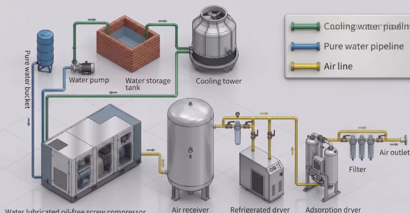
The high-pressure circuit is the primary specification challenge for most PET blowing compressed air systems. The required pressure (30–40 bar), the volume requirement, and the food-safe air quality standard (ISO 8573-1 Class 0) define a specification that eliminates most compressor technologies from consideration. Water-lubricated single-screw compressors are the preferred technology for this circuit because they achieve single-stage compression to 40 bar with isothermal efficiency and structural Class 0 oil-free air quality.
Key design parameters for the high-pressure circuit:
- Working pressure setpoint: Set the pressure 10–15% above the blow mold minimum requirement to compensate for distribution system losses and provide a stability margin during production peaks. If the blow mold requires 35 bar at the inlet, set the compressor at 38–40 bar.
- Flow rate sizing: Calculate the total main blowing air consumption as: (main blowing air volume per bottle) × (bottles per hour) × (safety factor of 1.1–1.15). Machine manufacturers publish specific air consumption figures per bottle size and production speed — use these as the primary sizing input.
- Air receiver sizing: A receiver of 10–15× the compressor’s per-minute output provides adequate pressure buffering against the pulsed demand of a rotary blow molder. Undersizing the receiver causes pressure fluctuations that affect bottle wall thickness uniformity.
- Downstream treatment: After the compressor and receiver, a refrigerated dryer and particulate filter are required. For direct food-contact applications, a desiccant dryer may be specified to achieve a pressure dew point of -40°C or lower.
Designing the Low-Pressure Circuit
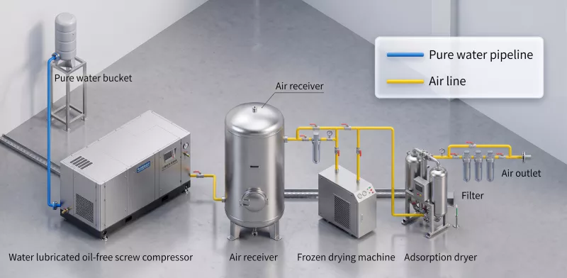
The low-pressure pre-blowing circuit is typically served by a standard 7–13 bar oil-free rotary screw compressor. Because pre-blowing air is in direct contact with the heated PET preform, it must also meet ISO 8573-1 Class 0 requirements — oil-injected compressors are not appropriate for this circuit either, regardless of the lower pressure involved. The low-pressure circuit is simpler to specify than the high-pressure circuit, as 7–13 bar oil-free screw compressors are widely available from multiple suppliers at this pressure range.
The low-pressure circuit shares the same downstream treatment philosophy as the high-pressure circuit — refrigerated dryer, particulate filtration — but at lower operating cost due to the reduced pressure ratio. The two circuits connect to separate headers at the blow molding machine, with dedicated pressure regulators and instrumentation for each.
Common Sizing Mistakes and How to Avoid Them
Several recurrent errors appear in PET blowing compressed air system designs. Awareness of these mistakes allows specification engineers to avoid them:
- Sizing from nameplate compressor ratings rather than measured machine consumption: Blow molding machine manufacturers publish air consumption figures that may not reflect actual consumption at your specific production speed, bottle size, and ambient conditions. Measure actual consumption on a running machine where possible; if not available, apply a 15% margin to manufacturer specifications.
- Ignoring distribution pressure losses: A long compressed air distribution run between the compressor and the blow molding machine can consume 3–8 bar in friction and fitting losses. The compressor pressure setpoint must account for these losses — setting the compressor at exactly the mold minimum requirement will result in underpressure at the mold inlet under peak demand conditions.
- Supplying both pre-blowing and main blowing from the high-pressure compressor: This single most common error in PET blowing system design wastes the energy invested in compressing pre-blowing air to 40 bar, then throttling it to 12 bar. Installing a dedicated low-pressure compressor for pre-blowing recovers this energy cost and typically pays back the additional equipment cost within 18–24 months.
- Undersizing the air receiver: A pulsed demand load from a high-speed rotary machine creates rapid pressure fluctuations in the compressed air header. An undersized receiver allows these fluctuations to reach the blow mold, causing cycle-to-cycle variation in bottle wall thickness. Receiver volume should be at minimum 10× the compressor’s per-minute output.
Pressure Specifications by Bottle Type
| Bottle Type | Pre-Blow Pressure | Main Blow Pressure | Notes |
|---|---|---|---|
| Standard water bottle (≤1.5L) | 8–12 bar | 22–30 bar | Thin wall, low resistance |
| Carbonated soft drink bottle | 10–18 bar | 35–40 bar | Thicker wall, base formation critical |
| Edible oil bottle | 10–15 bar | 30–38 bar | Medium wall, handle formation |
| Heat-resistant PET (hot-fill) | 12–20 bar | 38–40 bar | High crystallinity requires higher pressure |
| Large-format jug (5L+) | 15–25 bar | 35–40 bar | Heavy preform, extended stretch phase |
Understanding these pressure requirements by bottle type allows a single facility producing multiple formats to design a compressed air system with the correct pressure ceiling and determine when a single compressor can cover all formats versus when a dedicated high-pressure unit for demanding formats is warranted.
The Role of the High-Pressure Compressor in System Stability
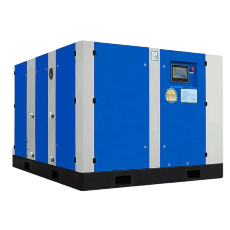
On a high-speed rotary blow molding line, the blow mold opens and closes at the rate of several cycles per second per cavity. At 20 cavities and 1,500 bottles per hour per cavity, the compressed air demand on the high-pressure circuit pulses at a frequency that can cause pressure fluctuations across the entire distribution header. A VSD compressor with tight pressure band control (±0.1 MPa) and adequate receiver volume maintains header pressure within the tolerance required for consistent bottle wall thickness — a quality parameter that directly affects bottle structural performance and material efficiency.
Fixed-frequency compressors are appropriate for lines with near-constant demand. VSD compressors — particularly dual-motor configurations — are better suited for lines with variable demand due to format changes, production speed adjustments, or multi-line supply configurations where the total demand on one compressor varies throughout the shift. The control response speed of modern VSD compressor controllers — typically adjusting motor speed within seconds of a pressure deviation — is fast enough for most PET blowing machines demand profiles.